|
|
 |
Custom Rollform Products offers more than rollform equipment and applications. We stand among the few manufacturers that design and build complete, turnkey fabrication systems. Unlike component integrators who piece together systems from various manufacturers, we engineer and manufacture every element you see in this video. Our team designs and integrates every programmed electrical, hydraulic, and pneumatic system in-house. This single-source approach guarantees you years of reliable service from one dedicated supplier.
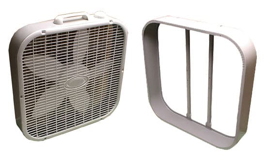
 Two Coil Fed Systems to form and assemble Box Fans complete from pre-painted mild steel.
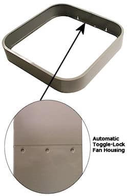
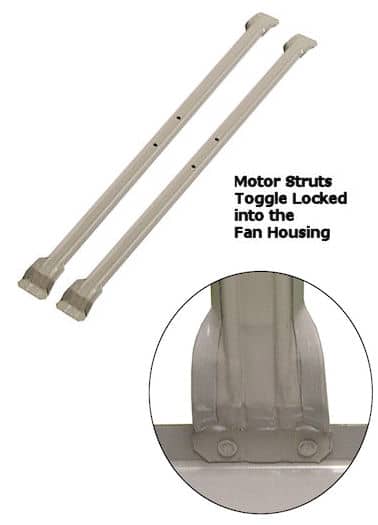
The System Advantage This complete Automation System integrates coil feed notching, punching, rollforming, and tangent form applications into one seamless workflow. Two Rollform Systems work simultaneously to manufacture the two essential fan components for this application. As the system fabricates the parts, it feeds them directly into a series of forming and assembly operations. These operations toggle-lock the housing, insert the Motor Mount Struts, and clinch-lock the Struts into the Fan Housing.
Streamlined Coil Processing The process begins with two specially designed uncoilers that handle 72” diameter coils. These uncoilers feed and payoff the coil strips directly from the horizontal skidded coil stack, minimizing downtime for coil changeovers. The system pulls pre-painted 22-gauge mild steel strips into two side-by-side Rollform Systems. These units pre-punch and notch the strip, rollform the Fan Housing and Motor Strut profiles, and finally cut and end-form the parts.
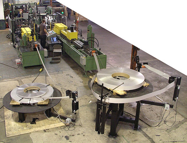
Special Uncoilers Handle 72″ Diameter Coils
 |
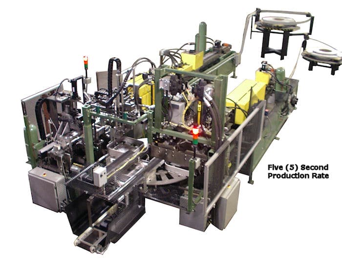
The system manufactures 12 complete fans per minute on a five-second production cycle. To match this speed, the corresponding Motor Mount Strut produces 24 parts per minute on a 2 ½ second cycle. Once the system rollforms and cuts the housing strip to length, it feeds the material directly into an automatic four-stage Tangent Forming Unit. This unit shapes the strip into a full-wrapper, four-sided housing with 4” radius corners. The Hydraulic Tangent Forming Unit then shuttles the part laterally through four forming heads, positions it for clinch locking, and loads it onto the four-station Assembly Turn Table. In the final stage, the Tangent Former clinch locks the part ends in three places. To maintain peak production rates, the Pick and Place Part Shuttle incorporates the Clinch Lock Press as it transfers the fan housing onto the four-station Assembly Unit. |
|
The system manufactures 12 complete fans per minute on a five-second production cycle. To match this speed, the corresponding Motor Mount Strut produces 24 parts per minute on a 2 ½ second cycle. Once the system rollforms and cuts the housing strip to length, it feeds the material directly into an automatic four-stage Tangent Forming Unit. This unit shapes the strip into a full-wrapper, four-sided housing with 4” radius corners. The Hydraulic Tangent Forming Unit then shuttles the part laterally through four forming heads, positions it for clinch locking, and loads it onto the four-station Assembly Turn Table. In the final stage, the Tangent Former clinch locks the part ends in three places. To maintain peak production rates, the Pick and Place Part Shuttle integrates the Clinch Lock Press as it transfers the fan housing onto the four-station Assembly Unit. Pick and PlaceThe first Pick and Place transfers the Motor Mount Struts from the Cutoff Press directly onto a Feed Transfer Conveyor every 2½ seconds. Immediately following this, the Transfer Conveyor indexes the Struts under a special two-part pick and place feed. Specifically, this unit feeds and positions two Motor Mount Struts directly into the Fan Housings. To ensure a precise fit, the two-part transfer rotates the Motor Mount Struts approximately 35° to clear the top Fan Housing flange. Consequently, the system positions them onto the Fan Housing and securely into the Fixture. Fan Strut Clinch Locking UnitOnce the system positions the Motor Mount Struts onto the Jig Fixture, the Fan Assembly indexes into the Fan Strut Clinch Locking Unit. In this stage, the special Clinch Lock Presses join and clinch lock both ends of the struts to the Fan Housing. Furthermore, the system secures each Motor Mount Strut with four clinch locks—two per end—resulting in eight total clinch locks every feed index cycle. As soon as the system completes the Fan Housings, it transfers them onto an Exit Conveyor. From there, the conveyor flips the part and feeds it onto the customer’s Conveyor System. Finally, the parts move directly to the Assembly Line for packaging on a just-in-time production schedule. |
 |
Certainly, it is encouraging to see manufacturers automate their lines. In addition, many companies now bring overseas production back to America. Originally, this process required 15 to 20 manual steps to produce fan housings. Furthermore, workers previously spot-welded parts together. After that, they had to paint the parts before final assembly.
However, the clinch lock application now allows fabrication from pre-painted coil strip. Consequently, the system sends parts directly to final assembly.
In fact, Custom Rollform Products serves as your one-stop supplier for all sheet metal applications. To ensure high quality, our team designs and engineers every component. Additionally, we plumb and program every system for years of reliable service. Ultimately, you receive total support from a single-source manufacturer. Therefore, call Custom Rollform Products today so we can design your custom system.
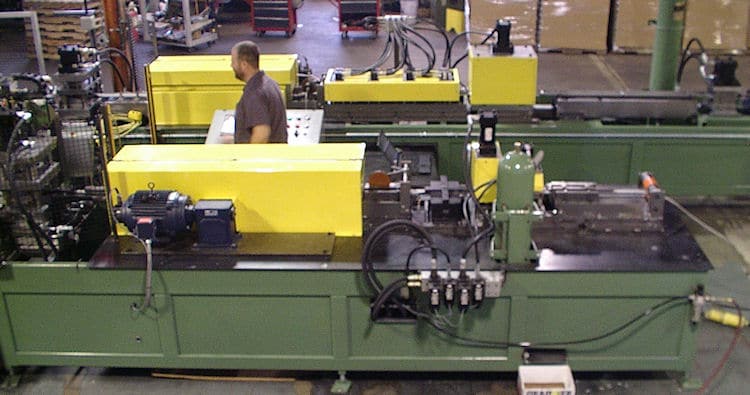 For Example Two Side by Side Rollform Systems Pre-punch / Notch Rollform & Cutoff